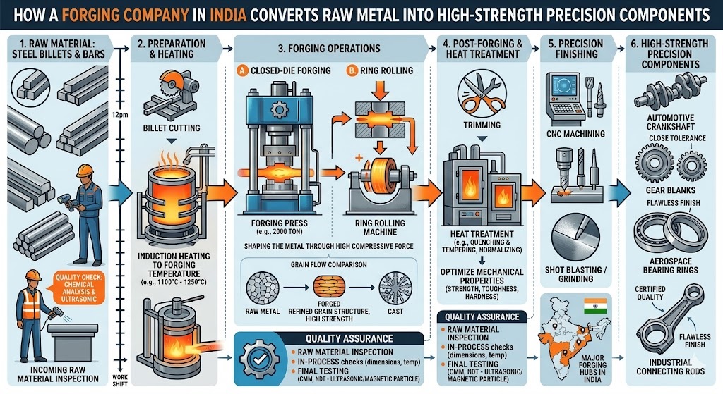

A metallographer sectioning a 4340 billet before and after forging sees two different metals even though the chemical analysis is identical. The as-rolled billet shows large, equiaxed prior austenite grains in the 40–80 µm range, with banding — alternating carbon-rich and carbon-depleted zones oriented along the rolling direction — and a grain boundary network that runs straight through the cross-section regardless of where the eventual component geometry will place its highest stress. Section the same steel after closed-die forging and normalising and the grain size has refined to ASTM 7–8 (22–16 µm range), the banding has broken up under compressive deformation, and the grain boundaries curve and follow the geometry of the part rather than running independently of it. The chemical analysis hasn’t changed. The mechanical properties have — fatigue limit up by 20–30%, Charpy impact up by 15–25 J at -29°C, and tensile strength up by 40–70 MPa over the hot-rolled bar it was cut from.
That transformation — from billet to high-strength component — is what a forging company in India engineers into the process, and it doesn’t happen automatically just because metal is heated and hit with a hammer.
What Forging Does to Metal That No Other Process Replicates
The metallurgical mechanism behind forging’s strength advantage is dynamic recrystallization — the simultaneous deformation and recrystallization of austenite grains that occurs when steel above its recrystallization temperature (approximately 950°C for medium carbon alloy steels) is subjected to compressive strain above the critical strain threshold for recrystallization. During the forging blow, the austenite grains deform plastically under compressive force; when the local strain exceeds approximately 0.4–0.6 true strain at temperatures above 1,050°C, new fine recrystallized grains nucleate at the deformed grain boundaries and grow to replace the deformed parent grains. The result is a grain size significantly finer than the original billet and considerably finer than what static annealing of the same steel would produce — dynamic recrystallization under forging conditions achieves grain sizes that isothermal annealing cannot replicate without much longer cycle times and controlled cooling rates.
What distinguishes a forging company in India producing genuine mechanical property improvements from one producing dimensionally correct shapes is control over the three variables governing dynamic recrystallization: deformation temperature, strain rate, and reduction ratio. If billet temperature drops below the recrystallization threshold before the finishing blow — which happens in a multi-blow sequence where the billet cools between strikes — the last blows deform austenite below recrystallization temperature, producing a mixed microstructure of fine dynamically recrystallized grains from early blows and work-hardened deformed grains from the final ones. Normalising partially repairs this, but static grain growth during normalising is slower and less uniform, and the microstructure is coarser than one that completed full dynamic recrystallization at the forge.
The reduction ratio amplifies or limits the recrystallization benefit. At 3:1 area reduction, accumulated strain through the billet thickness drives full dynamic recrystallization in most medium carbon alloy steels. At 2:1, strain at the forging centre may fall below the critical threshold, leaving a partially unrecrystallized core that normalising will only partially correct. Billet diameter selection relative to finished forging cross-section is therefore a process engineering decision at every forging company in India that takes its metallurgy seriously — not a stock management decision based on what diameter bar happens to be available.
Die Design as a Metal Flow Engineering Problem
The die cavity doesn’t just shape the component — it determines how the metal travels from the billet geometry to the finished geometry, and the path that metal takes during forging determines where the grain flow ends up relative to the stress-bearing surfaces of the finished part. A forging company in India with genuine die design capability treats each new part as a metal flow problem before it’s a dimensional problem.
For a helical gear shaft, the critical grain flow requirement is that the grain runs axially through the shaft body — parallel to the torsional and bending stress axes — and transitions continuously into each flange or boss feature without the grain being cut across by the die parting line. Finite element simulation of metal flow before die cutting predicts where the material velocity gradients are highest, which determines where grain shear occurs, and whether the final grain orientation at each critical surface matches the design’s fatigue assumption. A die parting line placed incorrectly relative to the shaft’s gear zone — across the tooth profile plane rather than perpendicular to it — causes the grain to run at 15–25° to the tooth root fillet plane, which reduces the effective fatigue limit at the tooth root by an amount that the stress analysis never accounted for because it assumed the grain was correctly oriented.
The blocking die is where material distribution for the finishing blow is set. A gear blank where the blocking die under-distributes material toward the outer rim enters the finishing die with insufficient stock at the tooth-forming zone, and the finishing die compensates by dragging material radially outward under high contact stress — shearing grain across the direction of motion rather than flowing it smoothly into the tooth geometry. The resulting grain orientation at the tooth flank is crossed rather than aligned, and the carburizing response becomes non-uniform because grain orientation affects carbon diffusion rate through austenite at each location.
From Forged Blank to Precision Dimension: The Tolerance Stack
The as-forged blank exits the finishing die at dimensional tolerances governed by IS 2004 — ±0.5 to ±1.6mm for linear dimensions below 100mm, depending on part weight and complexity. For a finished gear blank that requires a journal diameter at ±0.010mm (IT6), bore concentricity within 0.020mm TIR, and face runout below 0.015mm, the as-forged blank is the starting geometry from which four to six machining operations must deliver a final result that is 50–100 times tighter than what the forge produced. Every step in that sequence must preserve the gain of the previous step and avoid introducing new geometric error that the next step can’t correct.
Rough turning establishes the primary datum — typically the bore centreline for a gear blank — from which all subsequent dimensions are referenced. The cutting parameters here matter less for surface quality than for datum stability: a chatter-prone rough turn introducing 0.030mm radial vibration into the bore wall creates a datum that every subsequent dimension floats on, and the concentricity stack across the finished part can only be as good as that datum bore. A forging company in India running integrated machining on its own forgings knows the as-forged dimensional variation of the blank and sets rough turning parameters against actual variation ranges rather than nominal drawing values that assume a perfect blank.
Semi-finish turning brings the part to within 0.3–0.5mm of finished diameter on non-critical faces and 0.1–0.2mm on surfaces going to grinding. This is where secondary features — cross-holes, keyways, oil passages, chamfers — are machined, because they are faster and less tool-intensive to produce in the pre-hardened condition. A keyway in a 4340 shaft at 54 HRC requires a carbide end mill at reduced feed and depth of cut with cooling — the same keyway in the same shaft at 240 HB takes a HSS end mill at standard parameters in a fraction of the cycle time.
Heat treatment after semi-finish machining sets the final property profile. For a transmission counter shaft, the combination targets 28–34 HRC core with a carburized case at 58–62 HRC surface and 0.8–1.2mm effective case depth — a dual-zone profile where the surface resists contact fatigue under gear mesh loading and the core absorbs bending and torsional shock without brittle fracture.
Cylindrical grinding closes the tolerance gap between heat-treated semi-finish dimensions and the final IT6 requirement. The grinding wheel removes the last 0.05–0.15mm of stock, taking the journal from a turned surface at Ra 1.6 µm to a ground surface at Ra 0.4 µm, and the diameter from ±0.05mm at semi-finish to ±0.008mm at finish. The CNC grinding machine’s in-process air gauge measures the journal diameter at each pass and adjusts the infeed position to compensate for wheel wear and thermal expansion of the workpiece — without this compensation, thermal growth of the shaft during grinding produces an undersized final diameter as the part cools after the last pass.
The Capability Infrastructure Behind Consistent Output
The following table summarises the process control requirements at each stage of a forging company in India production sequence for a precision automotive drivetrain component. The Cpk values represent IATF 16949 minimum thresholds for special characteristics; the control methods represent the in-process infrastructure required to generate data demonstrating that those thresholds are being met in real time, not retrospectively.
| Stage | Critical Parameter | Specification | Min Cpk | Control Method |
| Billet cutting | Weight per billet | ±5g (4140, 50mm dia) | 1.33 | Precision scale, shift-start and mid-shift check |
| Induction heating | Surface-to-core temp variation | ±15°C max | 1.33 | Dual pyrometer: surface and exit-end contact |
| Forging — finish die | Flash weight variation | ±12g per part | 1.33 | 10-piece sample per batch, weight log |
| Normalising | Furnace zone temperature uniformity | ±14°C per AMS 2750 | 1.67 | TUS-verified quarterly, batch chart per load |
| Rough turning | Datum bore concentricity | 0.050mm TIR | 1.33 | CMM first-off + 5th piece |
| CNC Cylindrical Grinding | Journal diameter | ±0.008mm (IT6) | 1.67 | In-process air gauge, SPC chart |
| Nital Etch (post-grind) | Grinding burn absence | Pass/Fail | 100% | Visual exam under 40W incandescent light |
| CMM Final Inspection | GD&T stack per drawing | Per callout | 1.67 | CMM report, PPAP dimensional results |
Sendura Forge Pvt. Ltd., certified to IATF 16949:2016 and ISO 9001:2015, operates as a forging company in India from Rajkot with belt-drop hammer capacity from 1 to 3 tons, monthly production capacity of 800 metric tonnes, and a product range exceeding 700 part numbers — gear blanks, helical gear and shaft assemblies, balancing shafts, cross shafts, ring gear carriers, counter shafts, and coupling flanges in 4140, 4340, 20MnCr5, and EN series alloy steels — supplying DANA, Mahindra, Eaton, WABCO, Escorts, New Holland, TAFE, Bonfiglioli, RSB, and Setco, with the integrated forging, normalising, CNC machining, and QA/QC infrastructure that closing the tolerance gap from ±1.6mm at the forge to ±0.008mm at the grinder requires at production scale.
Conclusion
The transformation from a 4340 billet at 240 HB in a stockist’s rack to a transmission counter shaft at 58 HRC surface, 30 HRC core, and ±0.008mm on the bearing journal represents roughly eighteen process decisions made correctly in sequence — billet weight, induction temperature, reduction ratio, blocking die pre-form, finishing die parting line, normalising furnace load configuration, austenitising temperature, quench agitation, tempering temperature, rough turning datum, semi-finish concentricity, grinding wheel parameters, nital etch inspection. Each decision either preserves the quality potential of the step before it or introduces a deficiency that the next step either corrects at cost or inherits silently.
A forging company in India that has engineered the full sequence — not just the forging step and the grinding step but the connection between them and every stage in between — produces a finished component whose mechanical properties, dimensional accuracy, and documented quality history are all traceable to specific process decisions rather than to luck, inspection sorting, or the particular skill level of whoever was running the line that week. The difference between those two kinds of operations is visible in their Cpk data, in their PPAP first-time acceptance rate, and eventually in the field performance records that OEM customers use to determine which suppliers grow with a program and which ones get qualified out at the next sourcing review.